


MASTER OF COMPUTER APPLICATIONS
Course Code : MCS-012
Course Title : Computer Organisation and Assembly Language Programming
Assignment Number : MCA(I)/012/Assignment/15-16
Maximum Marks : 100
Weightage : 25%
Design a two bit counter (a sequential circuit) that counts from 00 to 10 only. Thus, the counter states are 00, 01, 10, 00, 01,…. You should show the state table, state diagram, the k-map for circuit design and logic diagram of the resultant design using D flip-flop or J-K flip flop.
Solution :
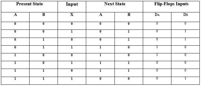
A sequential circuit is specified by a time sequence of external inputs, external outputs and internal flip-flop binary states. Thus firstly, a state table and state diagram is used to describe behaviour of the circuit.
|
Present State
|
Input |
Next State |
Flip-Flops Inputs |
|||
|
A
|
B |
X |
A
|
B |
DA |
DB |
|
0
|
0 |
0 |
0 |
0 |
0 |
0 |
|
0
|
0 |
1 |
0 |
1 |
0 |
1 |
|
0
|
1 |
0 |
0 |
1 |
0 |
1 |
|
0
|
1 |
1 |
1 |
0 |
1 |
0 |
|
1 |
0 |
0
|
1 |
0 |
1 |
0 |
|
1 |
0 |
1
|
1 |
1 |
0 |
0 |
|
1
|
1 |
0 |
1 |
1 |
0 |
0 |
|
1
|
1 |
1 |
0 |
0 |
0 |
1 |
There are 2 flip-flop inputs for counter i.e. A, B. The next state of flip-flop is given in the table. DA indicates the flip flop input corresponding to flip-flop-A. This counter requires 2-flip-flops.
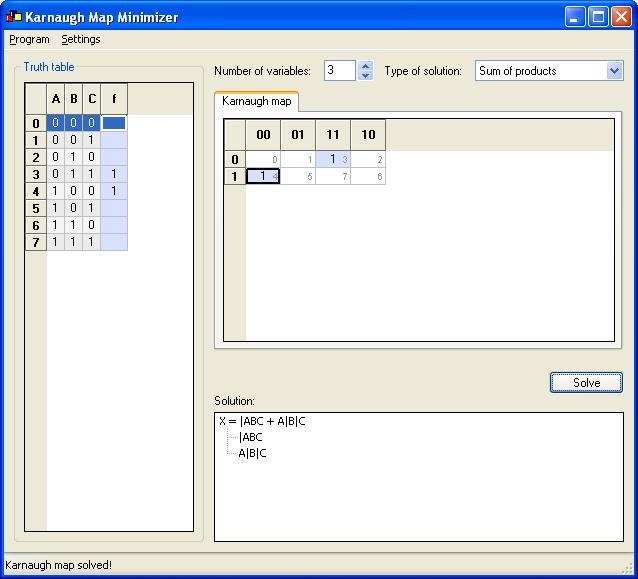
From this the flip flop input equations are simplified using K-Maps as shown below.
K-Map for DA is:
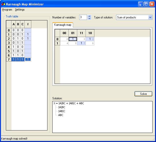
K-Map for DB is:
Thus, the simplified input equations for Counter are:
DA = |ABX + A|B|X
DB = |A|BX + |AB|X + ABX
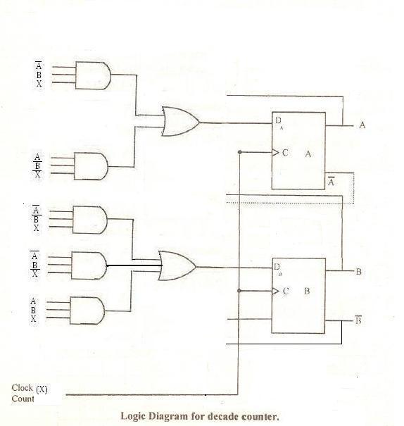
The logic circuit can be made with 2 D flip flops, 2 OR gates & 4 AND gates.