


Now we will write another Assembly program to find the LCM Least Common Multiplier of two 16-bit unsigned integers.
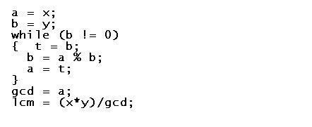
The above Logic is a C like Program to Find LCM we need its GCD or HCF first beacuse there is small Formula Shown above in a very simple way, So Just we will covert the logic into Assembly There are many things uncommon in the programing Language. There are No While Loops or Modules but this things are to be implemented in different ways.
Let’s identify variables needed for this program.
First variables will be the one which will hold the values present in the variables to be Added and it will be NUM1 and NUM2. Other variables will be holding the Output or Result of the Highest Common Factor or Greatest Common Divisor and Least Common Multiplier and it will be HCF and LCM So in all Four variables.
The identified variables are NUM1, NUM2 HCF and LCM.
First Line – DATA SEGMENT
DATA SEGMENT is the starting point of the Data Segment in a Program and DATA is the name given to this segment and SEGMENT is the keyword for defining Segments, Where we can declare our variables.
Next Line – NUM1 DW 1500
NUM2 DW 2500
HCF DW ?
LCM DW ?
We are initializing NUM1 to 1500 (Blank or Nothing after number) stands for Decimal ( By Default) ), NUM2 to 2500 ((Blank or Nothing after number) stands for Decimal ( By Default) ), HCF to ? (? stands for blank value). Detailed explanation is given below.
Next Line – DATA ENDS
DATA ENDS is the End point of the Data Segment in a Program. We can write just ENDS But to differentiate the end of which segment it is of which we have to write the same name given to the Data Segment.
Now, Selection of data type is DW data type the numbers which we are adding is 16-bit integers so DW is sufficient.
[codesyntax lang=”asm”]
DATA SEGMENT
NUM1 DW 1500
NUM2 DW 2500
HCF DW ?
LCM DW ?
ENDS
[/codesyntax]
In Assembly programming, the variable are all defined by bytes only.
DB – Define Byte (Size – 1 Byte)
DW – Define Word (Size – 2 Byte)
DD – Define Double word (Size – 4 Bytes)
DQ – Define Quad word (Size – 8 Bytes)
DT – Define Ten Bytes (Size – 10 Bytes)
NUMBER SYSTEM in Assembly Programming is Decimal, Octal, Hexadecimal, Binary.
In the Program, We are entering the values for the variables and Do arithmetical Operations like Addition, Subtraction, Multiplication and Division So the Computer should understand which kind of Number is entered. Hence there is a different letters for different Number Systems. O or o stands for Octal, H or h stands for Hexadecimal, B or b stands for Binary, D or d stands for Decimal. By default type of numbering system is Decimal. If you do not specify any letter then the number is understood to be Decimal (By default).
[codesyntax lang=”asm”]
DATA SEGMENT
NUM1 DW 1500
NUM2 DW 2500
HCF DW ?
LCM DW ?
ENDS
CODE SEGMENT
ASSUME DS:DATA CS:CODE
START:
MOV AX,DATA
MOV DS,AX
MOV AX,NUM1
MOV BX,NUM2
WHILE:MOV DX,0
MOV CX,BX
DIV BX
MOV BX,DX
MOV AX,CX
CMP BX,0
JNE WHILE
MOV HCF,AX
MOV CX,AX
MOV AX,NUM1
MOV BX,NUM2
MUL BX
DIV CX
MOV LCM,AX
MOV AH,4CH
INT 21H
ENDS
END START
[/codesyntax]
Explanation :
In this Assembly Language Programming, A single program is divided into four Segments which are 1. Data Segment, 2. Code Segment, 3. Stack Segment, and 4. Extra Segment. Now, from these one is compulsory i.e. Code Segment if at all you don’t need variable(s) for your program.if you need variable(s) for your program you will need two Segments i.e. Code Segment and Data Segment.
Next Line – CODE SEGMENT
CODE SEGMENT is the starting point of the Code Segment in a Program and CODE is the name given to this segment and SEGMENT is the keyword for defining Segments, Where we can write the coding of the program.
Next Line – ASSUME DS:DATA CS:CODE
In this Assembly Language Programming, their are Different Registers present for Different Purpose So we have to assume DATA is the name given to Data Segment register and CODE is the name given to Code Segment register (SS,ES are used in the same way as CS,DS )
Next Line – START:
START is the label used to show the starting point of the code which is written in the Code Segment. : is used to define a label as in C programming.
Next Line – MOV AX,DATA
MOV DS,AX
After Assuming DATA and CODE Segment, Still it is compulsory to initialize Data Segment to DS register. MOV is a keyword to move the second element into the first element. But we cannot move DATA Directly to DS due to MOV commands restriction, Hence we move DATA to AX and then from AX to DS. AX is the first and most important register in the ALU unit. This part is also called INITIALIZATION OF DATA SEGMENT and It is important so that the Data elements or variables in the DATA Segment are made accessable. Other Segments are not needed to be initialized, Only assuming is enhalf.
Next Line – MOV AX,NUM1
MOV BX,NUM2
The above two line of code is same as a=X and b=Y the Difference is that we are using Registers to Store Numbers, So we have t0 instruction MOV AX,NUM1 move NUM1 variable value to AX Register. MOV BX,NUM1 move NUM1 variable value to BX Register.
Next Line – WHILE: MOV DX,0
MOV CX,BX
WHILE: this will be starting point of while loop the condition cannot be written here So we write it Down and this is a LABEL and all the words ending in colon (:). i.e. MOV DX,0 here, DIV instruction is used to divide AX:DX for 16-bit and Not only AX register. Hence the unwanted value (garbage value) in DX register is removed by assigning ZERO to it. MOV CX,BX is to move BX register to CX register, Here We need a Temporary Storage register AX, BX and DX are used So we have only Option CX register.
Next Line – DIV BX
MOV BX,DX
In Assembly we can use Remainder as the Modules Output, So We have to Divide first to get Remainder. DIV BX Now DIV BX will Divide AX:DX register with NUM2 which is passed to BX register and Remainder of division is present in DX register so move the value to BX register. i.e. MOV BX,DX
Next Line – MOV AX,CX
MOV BX,CX is to move CX register to BX register, Here We are transfering a Temporary Storage in CX register to BX register.
Next Line –CMP BX,0
JNE WHILE
CMP BX,0 is used to Compare BX register to ZERO. JNE WHILE is used to Jump to Label WHILE if Not Equal when compared with CMP instruction prior to this one.
Next Line – MOV HCF,AX
MOV CX,AX
MOV HCF,AX is to move AX register (HCF of Two 16-bit Nos.) to HCF variable. MOV CX,AX is to move AX register to CX register as to preserve the HCF value to be used later in Equation to get LCM.
Next Line – MOV AX,NUM1
MOV BX,NUM2
MOV AX,NUM1 move NUM1 variable value to AX Register. MOV BX,NUM1 move NUM1 variable value to BX Register.
Next Line – MUL BX
DIV CX
MOV LCM,AX
MUL BX in this line BX register will be Multiplied with AX:DX register (BY DEFAULT) in which we have value of NUM1 is present. Now, This will give (X*Y). DIV CX in this line value in CX register will Divide AX:DX register (BY DEFAULT) in which the resultant value of (X*Y) is present. Now, This will give (X*Y)/HCF which is Result of LCM. MOV LCM,AX is to move AX register (LCM of Two 16-bit Nos.) to LCM variable.
Next Line – MOV AH,4CH
INT 21H
The above two line code is used to exit to dos or exit to operating system. Standard Input and Standard Output related Interupts are found in INT 21H which is also called as DOS interrupt. It works with the value of AH register, If the Value is 4ch, That means Return to Operating System or DOS which is the End of the program.
Next Line – CODE ENDS
CODE ENDS is the End point of the Code Segment in a Program. We can write just ENDS But to differentiate the end of which segment it is of which we have to write the same name given to the Code Segment.
Last Line – END START
END START is the end of the label used to show the ending point of the code which is written in the Code Segment.
Note :- In this Assembly Language Programming, We have Com format and EXE format. We are Learning in EXE format only which simple then COM format to understand and Write. We can write the program in lower or upper case, But i prepare Upper Case.
Screen Shots :-
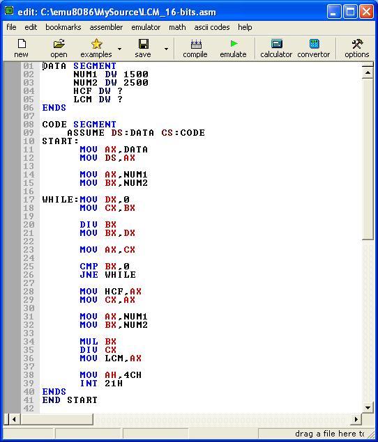
Before Execution :-

After Execution :-
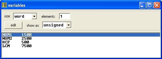
Note :- To see the variable and its value you have to click vars button in the emulator.
Note:- To understand program for sequence in detail Please SEARCH numerically example: ASSEMBLY01, ASSEMBLY02, etc.