


Design a decade counter using D-flipflop. Show all the steps involved 10m Dec2005
Decade counter
A BCD counter follows a sequence of ten states and returns to 0 after the count of 9. These counters are also called decade counters. This type of counter is useful in display applications in which BCD is required for conversion to a decimal readout.
|
Present State
|
Next State |
Flip-Flops Inputs |
|||||||||
|
A
|
B |
C |
D |
A |
B |
C |
D |
DA |
DB
|
DC
|
DD
|
|
0 |
0 |
0 |
0 |
0 |
0 |
0 |
1 |
0 |
0 |
0 |
1 |
|
0 |
0 |
0 |
1 |
0 |
0 |
1 |
0 |
0 |
0 |
1 |
0 |
|
0 |
0 |
1 |
0 |
0 |
0 |
1 |
1 |
0 |
0 |
1 |
1 |
|
0 |
0 |
1 |
1 |
0 |
1 |
0 |
0 |
0 |
1 |
0 |
0 |
|
0 |
1 |
0 |
0 |
0 |
1 |
0 |
1 |
0 |
1 |
0 |
1 |
|
0 |
1 |
0 |
1 |
0 |
1 |
1 |
0 |
0 |
1 |
1 |
0 |
|
0 |
1 |
1 |
0 |
0 |
1 |
1 |
1 |
0 |
1 |
1 |
1 |
|
0 |
1 |
1 |
1 |
1 |
0 |
0 |
0 |
1 |
0 |
0 |
0 |
|
1 |
0 |
0 |
0 |
1 |
0 |
0 |
1 |
1 |
0 |
0 |
1 |
|
1 |
0 |
0 |
1 |
0 |
0 |
0 |
0 |
0 |
0 |
0 |
0 |
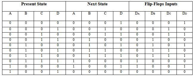
There are 4 flip-flop inputs for decade counter i.e. A, B, C, D. The next state of flip-flop is given in the table. JA & KA indicates the flip flop input corresponding to flip-flop-A. This counter requires 4-flip-flops.
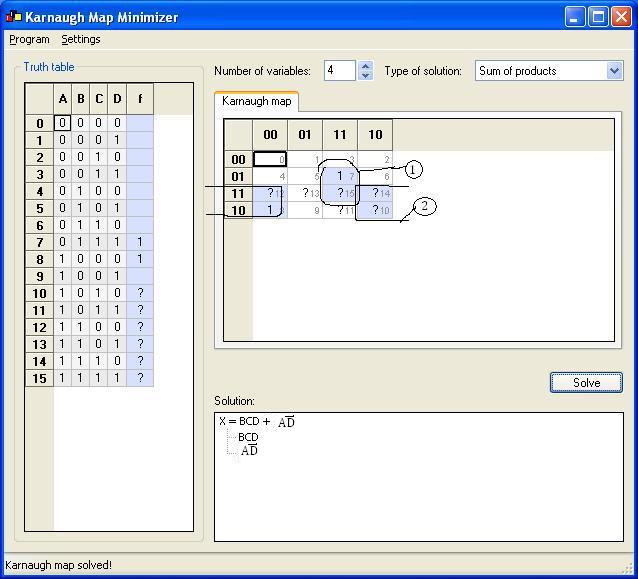
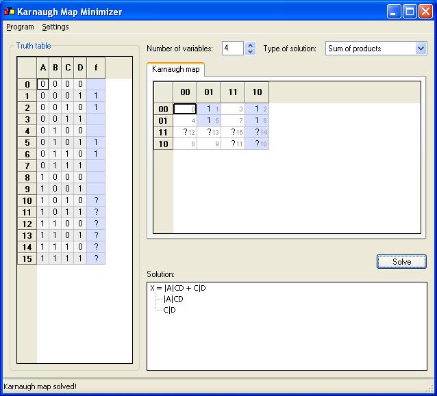
From this the flip flop input equations are simplified using K-Maps as shown below. The unused minterms from 1010 through 1111 are taken as don’t care conditions (X).
K-Map for Da is:
K-Map for Db is:

K-Map for Dc is:
K-Map for Dd is:

Thus, the simplified input equations for BCD counter are:
Da = BCD + A|D
Db = |BCD + B|C + B|D
Dc = |A|CD + C|D
Dd = |D
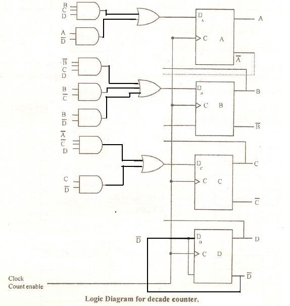
The logic circuit can be made with 4 D flip flops, 3 OR gates & 7 AND gates