


Draw the state table and the logic circuit for a 3-bit binary counter using D flipflop. 5m Jun2008
Binary counter
A digital circuit which has a clock input and a number of count outputs which give the number of clock cycles. The output may change either on rising or falling clock edges. The circuit may also have a reset input which sets all outputs to zero when asserted. The counter may be either a synchronous counter or a ripple counter.
|
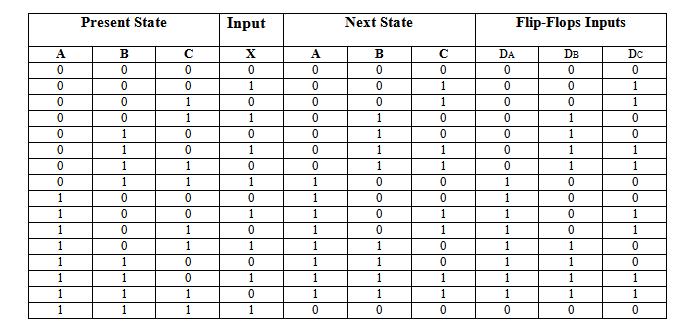
Present State
|
Input |
Next State |
Flip-Flops Inputs |
||||||
|
A |
B |
C |
X |
A |
B |
C |
DA |
DB |
DC |
|
0 |
0 |
0 |
0 |
0 |
0 |
0 |
0 |
0 |
0 |
|
0 |
0 |
0 |
1 |
0 |
0 |
1 |
0 |
0 |
1 |
|
0 |
0 |
1 |
0 |
0 |
0 |
1 |
0 |
0 |
1 |
|
0 |
0 |
1 |
1 |
0 |
1 |
0 |
0 |
1 |
0 |
|
0 |
1 |
0 |
0 |
0 |
1 |
0 |
0 |
1 |
0 |
|
0 |
1 |
0 |
1 |
0 |
1 |
1 |
0 |
1 |
1 |
|
0 |
1 |
1 |
0 |
0 |
1 |
1 |
0 |
1 |
1 |
|
0 |
1 |
1 |
1 |
1 |
0 |
0 |
1 |
0 |
0 |
|
1 |
0 |
0 |
0 |
1 |
0 |
0 |
1 |
0 |
0 |
|
1 |
0 |
0 |
1 |
1 |
0 |
1 |
1 |
0 |
1 |
|
1 |
0 |
1 |
0 |
1 |
0 |
1 |
1 |
0 |
1 |
|
1 |
0 |
1 |
1 |
1 |
1 |
0 |
1 |
1 |
0 |
|
1 |
1 |
0 |
0 |
1 |
1 |
0 |
1 |
1 |
0 |
|
1 |
1 |
0 |
1 |
1 |
1 |
1 |
1 |
1 |
1 |
|
1 |
1 |
1 |
0 |
1 |
1 |
1 |
1 |
1 |
1 |
|
1 |
1 |
1 |
1 |
0 |
0 |
0 |
0 |
0 |
0 |
There are 3 inputs for binary counter i.e. A, B, C. The next state of flip-flop is given in the table. DA indicates the flip flop input corresponding to flip-flop-A. This counter requires 3-flip-flops.
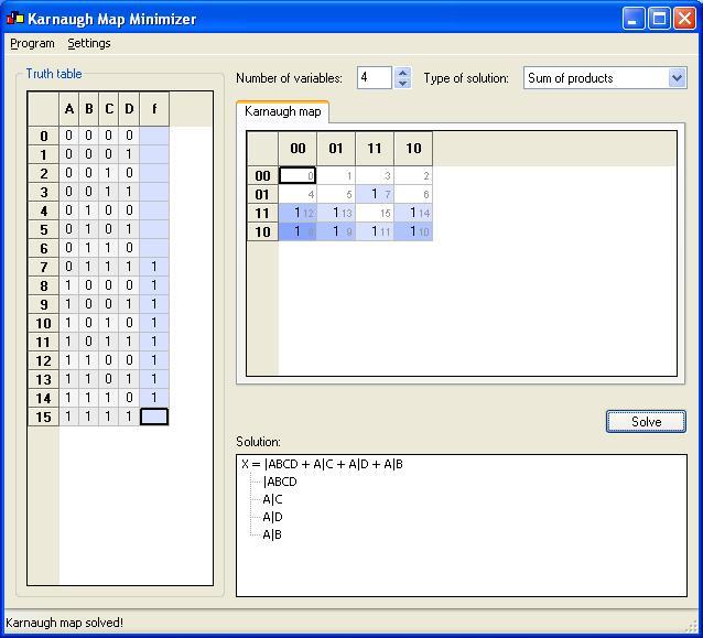
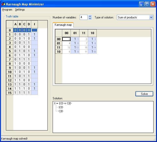
K-Map for Da is:
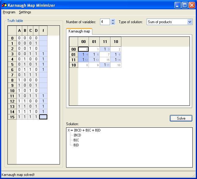
K-Map for Db is:
K-Map for Dc is:
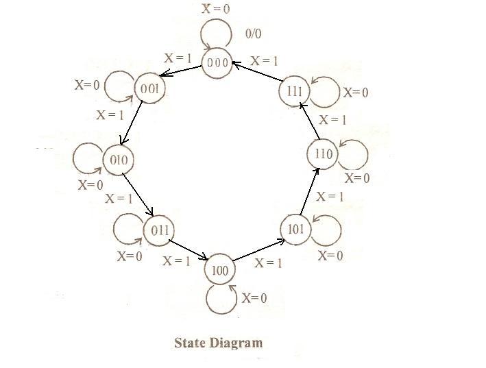
A sequential circuit is specified by a time sequence of external inputs, external outputs and internal flip-flop binary states. Thus firstly, a state table and state diagram is used to describe behaviour of the circuit
Thus, the simplified input equations for binary counter are:
DA = |ABCX + A|C+ AX + A|B
DB = |BCX + B|C + B|X
DC = |CX + C|X
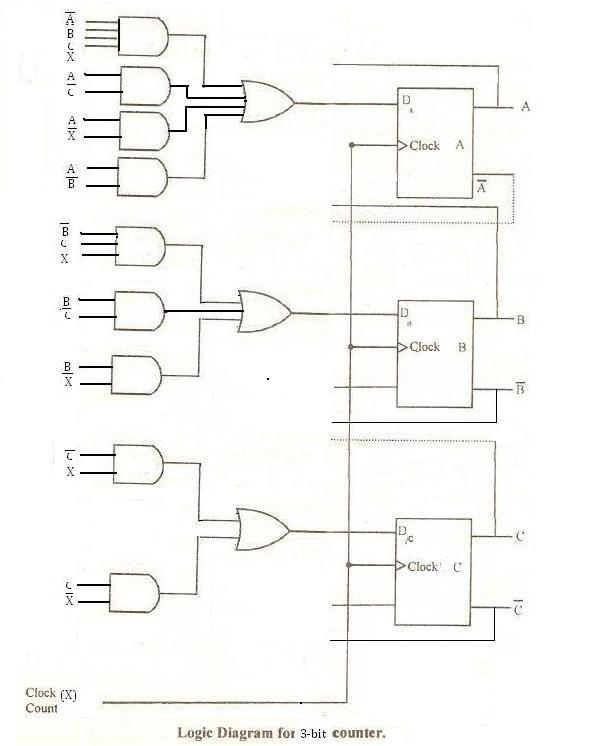
The logic circuit can be made with 3 D flip flops, 3 OR gates & 9 AND gates