MASTER OF COMPUTER APPLICATIONS
Course Code : MCS-012
Course Title : Computer Organisation and Assembly Language Programming
Assignment Number : MCA (2)/012/Assign /2014-15
Maximum Marks : 100
Weightage : 25%
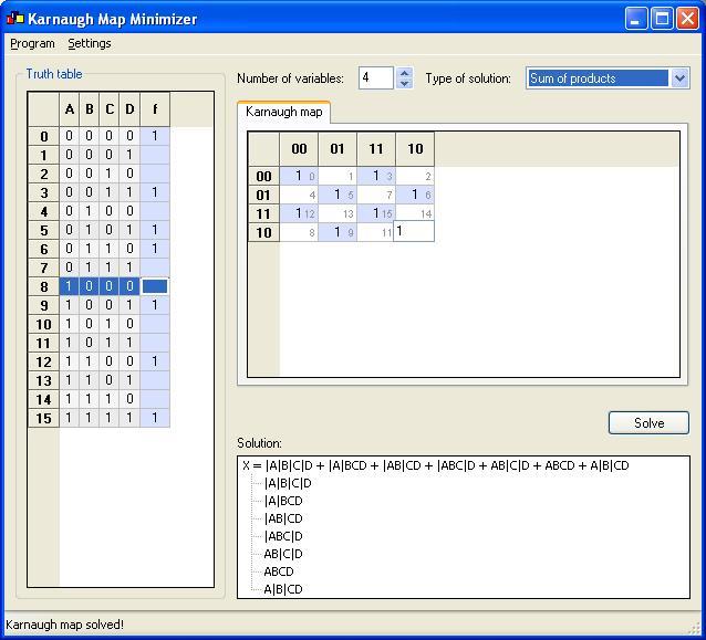
Use a Karnaugh’s map to design an odd parity generator circuit for 4 input bits.
Before Designing we should know inputs which is 4
That means 24 = 16 Combinations of outputs
Inputs are represented as ABCD
Output is represented by F and some times termed as Function
|
Decimal |
A |
B |
C |
D |
F (Function) |
|
0 |
0 |
0 |
0 |
0 |
|
|
1 |
0 |
0 |
0 |
1 |
|
|
2 |
0 |
0 |
1 |
0 |
|
|
3 |
0 |
0 |
1 |
1 |
|
|
4 |
0 |
1 |
0 |
0 |
|
|
5 |
0 |
1 |
0 |
1 |
|
|
6 |
0 |
1 |
1 |
0 |
|
|
7 |
0 |
1 |
1 |
1 |
|
|
8 |
1 |
0 |
0 |
0 |
|
|
9 |
1 |
0 |
0 |
1 |
|
|
10 |
1 |
0 |
1 |
0 |
|
|
11 |
1 |
0 |
1 |
1 |
|
|
12 |
1 |
1 |
0 |
0 |
|
|
13 |
1 |
1 |
0 |
1 |
|
|
14 |
1 |
1 |
1 |
0 |
|
|
15 |
1 |
1 |
1 |
1 |
Before proceeding we should know what odd parity is for ABCD inputs?
There are two types of parity even parity and odd parity
The parity is 0 or 1 depending upon total numbers of 1s
If count of 1s is even number then even parity = 0 and odd parity = 1
Similarly If count of 1s is odd number then even parity = 1 and odd parity = 0
After Finding out odd parity for ABCD inputs
We have Table as:-
|
Decimal |
A |
B |
C |
D |
F (Function) |
|
0 |
0 |
0 |
0 |
0 |
1 |
|
1 |
0 |
0 |
0 |
1 |
0 |
|
2 |
0 |
0 |
1 |
0 |
0 |
|
3 |
0 |
0 |
1 |
1 |
1 |
|
4 |
0 |
1 |
0 |
0 |
0 |
|
5 |
0 |
1 |
0 |
1 |
1 |
|
6 |
0 |
1 |
1 |
0 |
1 |
|
7 |
0 |
1 |
1 |
1 |
0 |
|
8 |
1 |
0 |
0 |
0 |
0 |
|
9 |
1 |
0 |
0 |
1 |
1 |
|
10 |
1 |
0 |
1 |
0 |
1 |
|
11 |
1 |
0 |
1 |
1 |
0 |
|
12 |
1 |
1 |
0 |
0 |
1 |
|
13 |
1 |
1 |
0 |
1 |
0 |
|
14 |
1 |
1 |
1 |
0 |
0 |
|
15 |
1 |
1 |
1 |
1 |
1 |
It’s can also be written as F =Σ (0, 3, 5, 6, 9, 10, 12, 15)
Only the decimal number where we find 1’s is shown in the Bracket.
Final Equation:-