


Decoder converts one type of coded information to another form. A decoder has ‘n’ inputs and an enable line (a sort of selection line) and 2n output lines. Let us see diagram of 3×8 decoder which decodes a 3 bit information and there is only one output line which gets the value 1 or in other words, out of 23= 8 lines only 1 output line is selected. Thus, depending on selected output line the information of the 3 bits can be recognized or decoded.
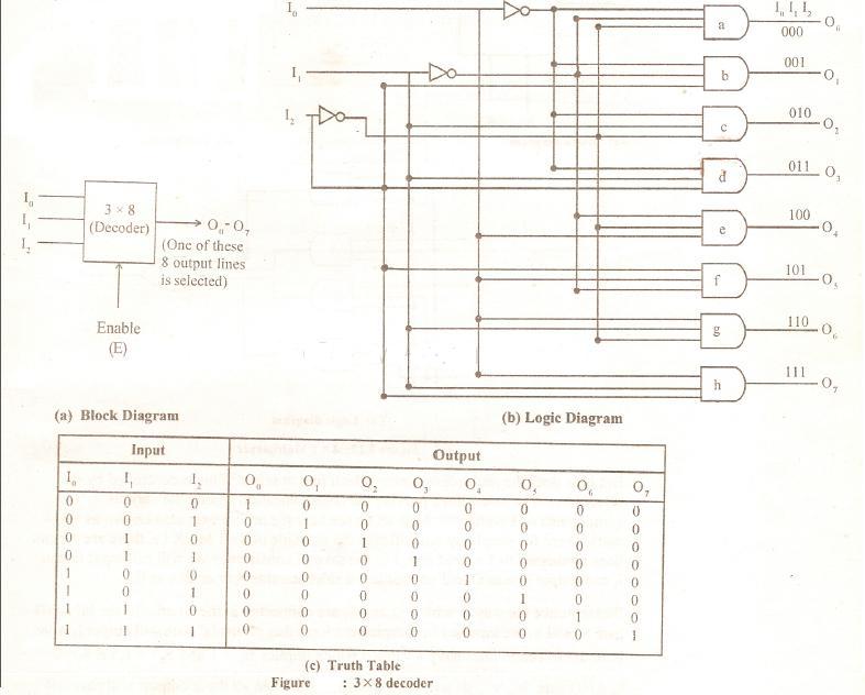
Please make sure while constructing the logic diagram wherever the values in the truth table are appearing as zero in input and one in output the input should be fed in complemented form e.g. the first 4 entries of truth table contains 0 in I0 position and hence I0 value 0 is passed through a NOT gate and fed to AND gates ‘a’, ‘b’, ‘c’ and‘d’ which implies that these gates will be activated / selected only if I0 is 0. If I0 value is 1 then none of the top 4 AND gates can be activated. Similar type of logic is valid for I1. Please note the output line selected is named 000 or 010 or 111 etc. The output value of only one of the lines will be 1. These 000, 010 indicates the label and suggest that if you have these I0 I1 I2 input values the labeled line will be selected for the output. The enable line is a good resource for combining two 3 x 8 decoders to make one 4 x 16 decoder.