


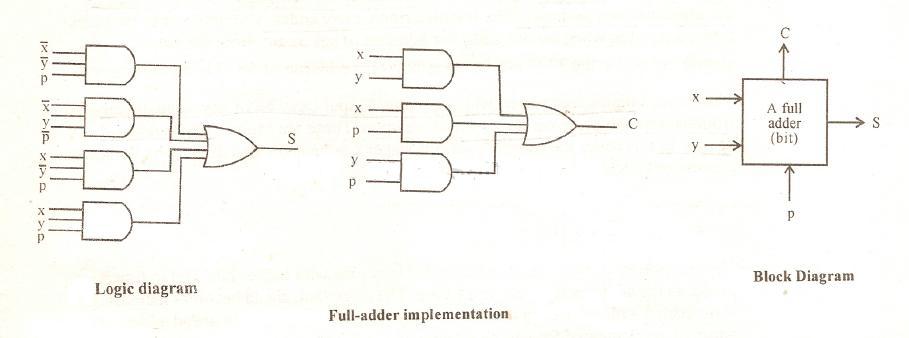
Draw the logic diagram of a full adder. Create a 2-bit adder-subtractor circuit using the block diagram of the full adder 6m Jun2006
A combinational circuit which performs addition of two bits is called a half adder, while the combinational circuit which performs arithmetic addition of three bits (the third bit is the previous carry bit) is called a full adder.
Truth Table: –

Logical and Block Diagram: –
K map for Carry: –
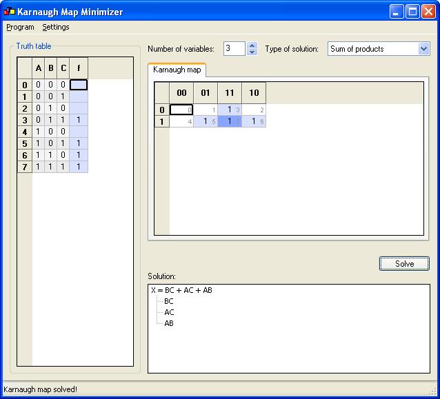
K map for Sum: –

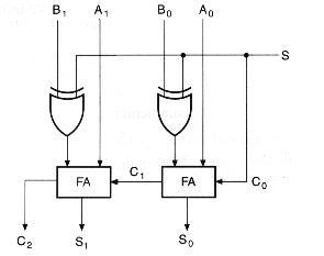
Adder – subtractor
The subtraction operation on binary numbers can be achieved by sequence of addition operations only i.e. to perform subtraction, A-B; we can find 2’s complement of B. This can be calculated using 1’s complemented & then adding 1 to it. Thus, a common circuit can perform the addition and subtraction operation. A 2-bit adder- subtraction circuit is shown in figure.
2-bit Adder – subtractor: –
Block Diagram